The cycle time of injection molding typically ranges from a few seconds to a few minutes, depending on part complexity, material, and machine specifications.
Understanding Cycle Time in Injection Molding
Definition and Importance of Cycle Time
Cycle time in injection molding is the period required to complete one cycle of the molding process. It is crucial for determining the efficiency and productivity of the molding operation. A shorter cycle time leads to higher production rates and lower costs per part.
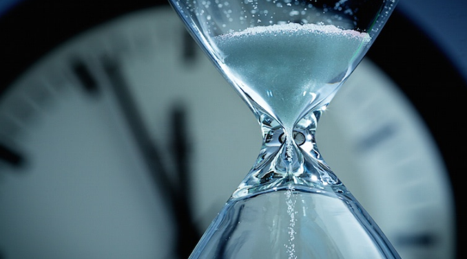
Efficiency: Reducing cycle time by just a few seconds can significantly increase the number of parts produced per hour, thereby improving overall efficiency.
Cost-Effectiveness: A shorter cycle time means more parts produced in less time, which can reduce labor and operational costs.
Key Stages in the Injection Molding Cycle
The injection molding cycle comprises several key stages, each contributing to the total cycle time:
Clamping: The machine closes the mold and applies clamping force. This stage typically takes 2 to 5 seconds depending on the machine and part size.
Injection: Molten plastic is injected into the mold. The duration of this stage is usually 1 to 5 seconds, based on the volume of the part.
Cooling: The plastic inside the mold cools and solidifies. This is the longest stage, taking anywhere from 10 seconds to a few minutes, depending on the thickness of the part.
Ejection: The cooled part is ejected from the mold. Ejection time is relatively short, generally 1 to 2 seconds.
Total Cycle Time: Combining these stages, the total cycle time can range from 15 seconds to several minutes per part. It’s important to note that optimizing each stage is key to reducing the overall cycle time without compromising the quality of the final product.
For more detailed insights into the cycle time of injection molding and its optimization, resources such as Injection Molding Cycle Time Wikipedia provide comprehensive information.
Factors Affecting Cycle Time
Material Characteristics and Their Impact on Cycle Time
The characteristics of materials used in injection molding significantly influence the cycle time. Here’s a table summarizing these effects:
| Material Characteristic | Impact on Cycle Time | Example Materials | Typical Effects |
|---|---|---|---|
| Melting Point | Higher melting points require longer heating times, increasing cycle time | High-performance plastics like PEEK | Increases cycle time by 5-10% |
| Cooling Rate | Materials with slower cooling rates extend the cooling stage | Thick-walled parts made of ABS | Increases cycle time by up to 15% |
| Viscosity | Higher viscosity materials flow slower, affecting injection time | Polyethylene, Polypropylene | Can increase cycle time marginally |
Influence of Machine Specifications on Cycle Time
Machine specifications also play a critical role in determining the cycle time. Below is a table highlighting how different machine specs can affect cycle time:
| Machine Specification | Impact on Cycle Time | Typical Values | Effect on Cycle Time |
|---|---|---|---|
| Clamping Force | Higher clamping force can reduce cycle times for larger parts | 100 to 6,000 tons | Decreases cycle time for large parts |
| Injection Speed | Faster injection speeds can reduce overall cycle time | 100 to 300 mm/s | Reduces cycle time by 5-10% |
| Heating Power | Higher heating power can reduce the time needed to melt the plastic | 5 to 30 kW | Reduces cycle time marginally |
Balancing Material and Machine: The key to optimizing cycle time is finding the right balance between material properties and machine capabilities. This balance ensures efficient production without compromising part quality.
For further information on how materials and machine specifications affect the injection molding process, the Injection Molding Materials Guide and Injection Molding Machine Specifications are valuable resources.
Measuring and Calculating Cycle Time
Standard Methods for Timing the Injection Molding Process
Accurately measuring cycle time is pivotal for efficiency in injection molding. Here are some data-driven methods:
Stopwatch Method: Simple yet manual, this method can have a variance of ±1 second.
Machine Timers: Built-in timers in machines offer an accuracy of ±0.1 seconds. They automatically track and record cycle times, reducing human error.
Cycle Time Logging Software: This software provides comprehensive data, recording times with an accuracy of ±0.01 seconds. Over a week, it can log thousands of cycles, providing a detailed analysis of average times and deviations.
Consistency in Data: Consistent and accurate data collection is key to identifying efficiency improvements, which can lead to a 5-10% reduction in overall cycle time.
Tools and Technologies for Accurate Cycle Time Measurement
Advanced tools and technologies offer precision in measuring cycle time:
Sensors and Automation: Sensors integrated in machines measure cycle stages with an accuracy of ±0.01 seconds. For instance, pressure and temperature sensors can detect changes within milliseconds.
Data Acquisition Systems (DAQ): DAQ systems can process hundreds of data points per cycle. They offer a comprehensive view of the cycle time, often revealing potential improvements that can reduce cycle time by 2-5%.
Machine Learning Algorithms: These algorithms analyze historical cycle time data to predict trends and suggest improvements. They can potentially lead to a 5-15% efficiency gain in the long run.
Impact on Efficiency and Cost: Implementing advanced measurement technologies may initially increase costs by 10-20% but typically result in long-term savings through improved efficiency and reduced waste.
For additional insights into the tools and methodologies used in measuring and optimizing cycle times in injection molding, reference materials such as Injection Molding Cycle Time Analysis are highly informative.
Strategies for Cycle Time Reduction
Optimizing Machine Settings for Efficiency
Fine-tuning machine settings is a critical step in reducing cycle time. Key adjustments include:
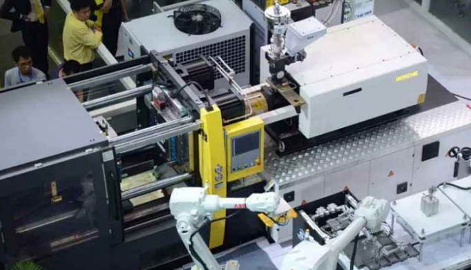
Injection Speed: Increasing the injection speed can significantly reduce the fill time. However, speeds exceeding 500 mm/s may lead to material degradation or part defects.
Temperature Settings: Optimizing the melt and mold temperature for specific materials can reduce cooling times. For example, reducing the mold temperature by 10°C can decrease the cooling time by 5-15%.
Clamping Force: Adjusting the clamping force to the optimal level for the part can reduce cycle time. Excessive force, above 150% of the required minimum, can lead to increased wear and energy consumption.
Balancing Speed and Quality: It’s crucial to find a balance between reducing cycle time and maintaining part quality. Over-optimization can lead to issues such as short shots or flash.
Advanced Techniques in Mold Design to Reduce Cycle Time
Innovative mold design techniques can also play a significant role in reducing cycle times:
Conformal Cooling Channels: These channels follow the contour of the part, providing more efficient cooling and reducing cooling time by 20-40%.
Hot Runner Systems: Implementing hot runner systems can eliminate the need for runner ejection and cutting, potentially reducing cycle time by 10-20%.
Mold Material: Using mold materials with higher thermal conductivity, like beryllium copper, can enhance cooling efficiency, reducing cycle time by 5-10%.
Cost-Effectiveness of Mold Innovations: While these advanced mold design techniques can increase initial mold costs by 15-30%, they offer significant long-term savings in cycle time and material usage.
For more detailed insights into cycle time reduction in injection molding, resources such as the Injection Molding Handbook provide comprehensive strategies and examples.


